Research article | DOI: https://doi.org/10.31579/2694-0248/019
1 Biomechanical Engineering Laboratory (LEBm) of University Hospital, Department of Mechanical Engineering, Federal University of Santa Catarina, Florianópolis, SC, Brazil.
2 National Institute for Traumatology and Orthopedics Jamil Haddad, Rio de Janeiro, RJ, Brazil.
*Corresponding Author: Carlos Rodrigo de Mello Roesler, Biomechanical Engineering Laboratory (LEBm) of University Hospital, Department of Mechanical Engineering, Federal University of Santa Catarina, Florianópolis, SC, Brazil.
Citation: Vinícius V. Zanard.i, Matheus Guimarães JA, João Victor da Silveira Möller, Carlos Rodrigo de Mello Roesler (2022). Medial Locking Plate Can Increase the Fixation Stability of Vertical Femoral Neck Fracture in Young Adults? J. Clinical Orthopedics and Trauma Care, 4(2); DOI:10.31579/2694-0248/019
Copyright: © 2022 Carlos Rodrigo de Mello Roesler, This is an open access article distributed under the Creative Commons Attribution License, which permits unrestricted use, distribution, and reproduction in any medium, provided the original work is properly cited.
Received: 19 November 2021 | Accepted: 30 December 2021 | Published: 10 January 2022
Keywords: vertical shear femoral neck fractures; biomechanical testing; micromovements
Vertical femoral neck fractures in young adults are usually caused by a high-energy trauma. These injuries are difficult to stabilize due to significant shear forces acting on the fracture site. Their treatment is challenging and has a high risk of complications, such as fixation failure, malunion, nonunion and avascular necrosis of the femoral head. In recent years, several studies have focused on the use of direct reduction of vertical femoral neck fractures in young adult patients. This technique allows for anatomical reduction as well as the placement of an intra-articular implant to avoid shear forces at the fracture site. The aim of this study was to evaluate, based on in vitro experimental tests, the biomechanical stability provided by three different fixation methods: (i) dynamic hip screw with derotation screw, (ii) cannulated screws with a conventional medial bone plate and (iii) cannulated screws with a locked medial bone plate. For the biomechanical tests, these techniques were applied to reduce the vertical osteotomy performed on synthetic bones for later verification of the mechanical behavior under axial cyclic loading and destructive axial loading. There were no statistical differences in stiffness, micromovement displacement and mechanical strength during the biomechanical comparison of the fixation methods. Therefore, we conclude that the use of a conventional medial bone plate associated with cannulated screws, with a transverse trochanteric screw, supports the mechanical demand while the fracture is healing and this option can be used to stabilize vertical femoral neck fractures in young patients.
Vertical femoral neck fractures in young adults are usually caused by a high-energy trauma. Femoral neck fractures can be classified based on the degree of verticality using the Pauwels [1] classification, where a higher grade indicates a more vertical orientation of the fracture. When deviated, it is difficult to reduce this type of fracture through the indirect technique. In these situations, it is necessary to open the capsule and perform a direct intervention to guarantee a high quality of reduction, considered one of the most important factors for a surgery to succeed [2]. Research is also centered on the osteosynthesis techniques, since implants suffer from significant shear forces acting on the fracture site, leading to a risk of fixation failure and nonunion3. In recent years, several studies have been focused on the use of the direct reduction of vertical femoral neck fractures in young adult patients. This technique allows for anatomical reduction as well as the placement of an intra- articular implant to avoid shear forces at the fracture site [4, 5, 6, 7, 8]. Different authors suggests placing a one-third tubular plate at the inferior vertex of the fracture site, associated with cannulated screws that are conventionally positioned at the proximal lateral part of the femur, passing through the bone towards the femoral head. Regarding the vertical femoral neck stabilization, and according to in vitro biomechanical studies previously published, this combination provides results similar to those of the sliding hip screw and the procedure using isolated cannulated screws [9.10, 11]. The evaluation of the femoral neck fixation stability applying different techniques, based on the quantification of the movement that occurs in the fracture site plane during the application of cyclic loads (with the intention of reproducing the load-unload condition during human gait), has been the center of attention in recent researches [33, 14, 13, 36]. The aim of this study was to verify whether the use of cannulated screws with a locked medial bone plate increases the fixation stability of vertical femoral neck fractures in young adults when compared to the use of cannulated screws with a conventional medial bone plate and the use of dynamic hip screw with a derotation screw. The starting hypothesis is that the placement of the locked medial plate would add greater stability to the system, preventing the femoral neck shortening.
The experimental comparison between the three fixation methods was performed through biomechanical tests under a cyclic loading followed by a destructive (ultimate) loading to measure the mechanical resistance of the fixations. The interfragmentary movement at the fracture site was the main variable observed during the cyclical phase. The secondary variables analyzed included: (i) the initial stiffness of the bone-implant systems, calculated at the beginning of the cyclical phase; (ii) the final stiffness (calculated after the loading cycles); and (iii) the maximum load supported by the bone-implant systems. Three fixation group methods were defined for the biomechanical comparison:
Group 1 - Dynamic hip screw with derotation screw (DHS + DS);
Group 2 - Cannulated screws with medial bone plate (CSMP); and
Group 3 - Cannulated screws with locked medial bone plate (CSLMP).
Synthetic bone and implants
The 4th generation medium-sized synthetic bone (Sawbone, Pacific Research Company, Vashon Island, Washington 98070, USA), with a 17 PCF cellular foam core, was used to replace a real bone. The cervico-diaphyseal angle of the synthetic bone was 120°. The cannulated screws inserted in the implants had a 7.0 mm diameter and 19 mm thread. The one-third tubular plates were fixed with cortical screws with a 3.5 mm diameter. The locked cortical screws had head threads designed to be threaded into the tubular holes.
The derotation screws (DS) had a trabecular thread with a 6.5 mm diameter and 16 mm length. The sliding hip screw (DHS) had a 12.5 mm diameter and 28 mm thread, while the DHS plate was fixed at an angle of 135°, containing three oblong holes. All implants were manufactured with stainless steel (ASTM F138) and donated by the Hexagon Indústria e Comércio de Implantes Orthopedic company (Itapira, São Paulo - Brazil).
Osteotomy pattern and osteosynthesis screw fixation
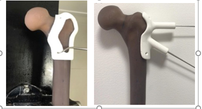
The osteotomy was performed at a 70° angle in the coronal plane. In the transverse plane, the osteotomy was performed perpendicular (90º) to the femoral neck axis. In order to create a vertical fracture pattern for the femoral neck, based on the tomographic image of the selected synthetic bone, a cutting/osteotomy template was designed and fabricated using additive manufacturing (Figure 1a). Regarding the cannulated screws technique, a guide was also manufactured to ensure that the cannulated screws would always be placed in the same position. To do so, a radiograph of the guide wires was obtained by radioscopy and an initial model was created based on computed tomography. With the tomographic images in hand, it was possible to print the specific guide to position the cannulated screws (Figure 1b).
To position the mechanical testing device, the specimens were osteotomized in the diaphyseal region of the femur, in a distal region, 190 mm from the tip of the greater trochanter. For the osteotomy procedure, the 3D printed guide was positioned on the femoral greater trochanter and with the aid of an experienced orthopedic surgeon the cut was carried out with an oscillating saw.
The osteosynthesis assemblies were executed with the aid of an orthopedic surgeon, as follows:
Group 1 - Dynamic Hip Screw with Derotation Screw (DHS + DS)
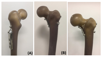
A sliding screw (12.5 mm diameter and 28 mm thread) and derotational screw (6.5 mm diameter and 16 mm thread) were used. The sliding screw was placed in the synthetic bone next to the DHS plate, right at the center line of the femoral shaft (Figure 2a). This technique did not require a guide since the DHS plate has a fixed angle of 135°.
Group 2 - Cannulated Screws with a Contoured Conventional Medial Plate (CSMP)
Three cannulated screws (7.0 mm diameter) and three 3.5 mm cortical screws (without head threads) were used. One of the cortical screws was fixed in the proximal region of the fracture site and the other two in the distal region (Figure 2b). The conventional medial bone plate was fixed on the osteotomy inferior vertex. The 3D printed guide was used for the placement of the cannulated screws.
Group 3 - Cannulated Screws with a Contoured Medial Locking Plate (CSLMP)
Three cannulated screws (7.0 mm in diameter) and three 3.5 mm cortical screws (with head threads) were used. One of the cortical screws was fixed in the proximal region of the fracture site and the other two in the distal region. The medial bone plate was previously modeled, according to the femoral medial cortex shape, to avoid damage to the threads of the holes, and fixed directly at the inferior vertex of the osteotomy (in the medial part of the femoral neck).
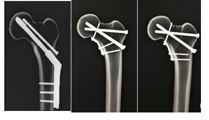
In all cases, the correct positioning of the screws and the medial plate were verified based on radiographs of the specimens (Figure 3). Three bone-implant systems (n = 3) were tested for each of the three fixation method groups.
Biomechanical Tests
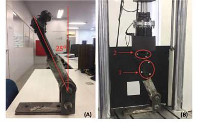
In order to properly apply the load on the specimens, the bone-implant models were individually cemented into a metallic cup-shaped device, which was then fixed to the base of the testing machine. The MTS Bionix model 370.02 machine was used to apply the load. The mechanical axis of the femur was aligned at an angle of 25° (valgus) with respect to the test device base (Figure 4) to simulate a normal one-legged weight-bearing stance12. A flat face device was used on the machine actuator to apply the compressive load, allowing a free translation of the femoral head during the compression phase. For the biomechanical test, each specimen was preloaded to 200 N at a rate of 5 N/s. The load was then increased to 550 N. The sinusoidal13 cyclical axial loading was performed with a force amplitude of 450 N (ranging from 100 N to 1000 N, and average load of 550 N) for 1000 cycles at a frequency of 1 Hz, which corresponds to the average frequency in human gait (ISO 14242- 1). The initial stiffness of the bone-implant system was calculated based on data obtained from the force-displacement curve at the preload stage. A vertical femoral head displacement greater than or equal to 5 mm was adopted as a failure criterion during the cyclic loading14. At the end of the cyclical stage, each bone-implant system that did not fail went through a monotonic compressive quasi-static loading up to the ultimate load of the system, according to a displacement control at a rate of 5 mm/min. The final system stiffness was calculated with data obtained from the force-displacement curve. The failure criterion adopted was a 75% drop in the applied force. A greater force required to reach failure indicates a greater resistance of the system.
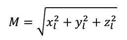
The stiffness values determined during quasi-static loading (preload) and destructive loading (after the cycle loads) were calculated based on a linear regression of the initial data in the force-displacement curve, considering a 0.2 % offset. This offset was adopted to give an approximation of the elastic and plastic regions of the curve for the system. The slope of the line curve obtained from the linear regression (in the elastic region) was used to determine the system stiffness15, 16. It is important to mention that the stiffness value is associated with the vertical force applied by the machine and the vertical displacement of the actuator. The relative displacement at the fracture site was determined according to Equation 1, which is used to calculate the average displacement (M) of the fracture fragments in the tangential and axial plane. The mean displacement in the normal (axial) direction on the fracture plane and the relative motion of the femoral head in the tangential (shear) directions are represented by the following variables: xl (axial), yl and zl. Equation 1 provides the resulting average displacement (M) in these three directions14, which is the magnitude of a vector in three dimensions.
The micromovements at the fracture were measured by the Optitrack capture system (model V120:Trio). This system allows the measurement of displacements and angulations of a rigid body, based on the stereoscopic processing of images obtained by an optical system with three cameras positioned at known distances and angulations. These cameras capture the movements of reference points (called “trackers”) positioned on the object. One tracker (with three reflectors) was positioned on the metaphysis of the synthetic bone and another on the femoral head. The relative movement between these two parts was then monitored (Figure 4). The tracking process occurs through the identification of the barycenter of each set of three reflectors, positioned in a triangular shape. The reflectors were attached to small wooden rods with a diameter of 3.5 mm. These wooden rods were inserted in drilled holes on the synthetic bone. The accuracy of the tracking system was optimized by painting the synthetic femurs in matte black and covering the reflective parts of the testing machine with black cardboard.
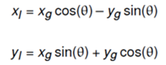
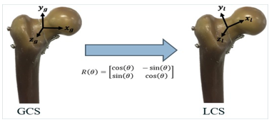
The displacements were measured by the Optitrack system according to a global coordinate system (GCS), in which the base of the testing machine is the referenced plane. The displacement on the fracture plane14 is verified based on a local coordinate system (LCS), which can be measured by applying a rotational matrix to the GCS. A 45° counterclockwise rotational matrix was applied along the zg axis (Figure 5). Thus, it was possible to obtain the xl, yl and zl variables in the LCS.
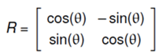
Considering that only the x and y components vary during the transformation from global to local coordinates, the displacement values of the LCS can be obtained using a rotational matrix in two dimensions, represented by Equation (3).
The displacement on the global system is represented by the variables xg and yg, as well as xl and yl for the local system. The use of a rotational matrix will result in the following equations for the LCS variables:
It should be noted that in the GCS the x direction corresponds to a transverse plane movement, the y direction to a frontal plane movement and the z direction to a sagittal plane (anteroposterior) displacement. Regarding the LCS, the xl plane corresponds to a movement towards the femoral neck, the yl plane to a superior-inferior shearing movement along the fracture line and the zl plane to an anteroposterior shear movement.
In order to compare the micromovement amplitude values during the cyclic loading, four different cyclic instants were chosen and compared: cycle 70, cycle 420, cycle 670 and cycle 920. These instants cover the initial, intermediate and final moments of the cyclic loading phase.
Statistical analysis
The statistical differences on comparing the three experimental groups, regarding stiffness, displacement amplitude and mechanical strength, were evaluated through the analysis of variance (ANOVA) method, with a confidence level of P < 0>
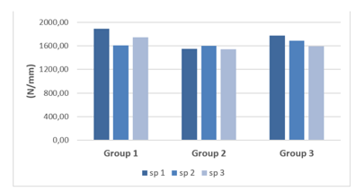
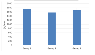
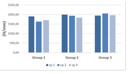
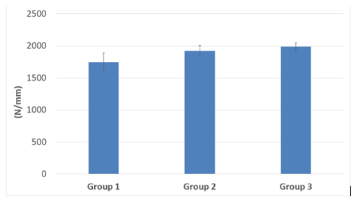
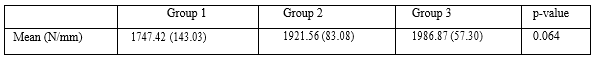
The initial stiffness values for each specimen are shown in Figure 6 and the mean values can be observed in Figure 7 and Table 1. The difference in the mean stiffness values for the three groups is not statistically significant (P > 0.05).

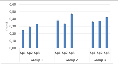
The displacement amplitude at the fracture site (LCS) for each specimen of the three groups is shown in Figure 8. Table 2 shows the mean amplitude of the displacement at the fracture site (LCS) for each group, which was calculated using data for the four different cycle instants. The difference in the displacement values for the groups is not statistically significant (P > 0.05)
Standard deviation shown in parentheses beside the mean stiffness of each group.
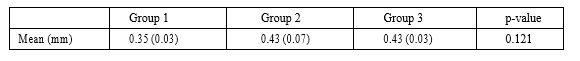
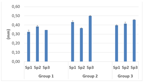
Figure 9 and Table 3 show the behavior related to the vertical shear movement (from the top to the bottom) along the fracture line, represented by yl (LCS), for each fixation technique. The difference in displacement amplitudes for the groups was not statistically significant (P > 0.05).

Standard deviation shown in parentheses beside the mean displacement of each group.
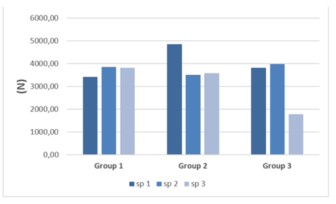
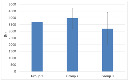
The mechanical resistance values (maximum supported load) obtained for each specimen of the three groups are shown in Figure 10 while the mean values for each group are shown in Figure 11 and Table 4. The difference in the mean resistance values obtained for the groups is not statistically significant (P > 0.05).

Standard deviation shown in parentheses beside the mean resistance of each group.
The final stiffness values obtained for the specimens and the arithmetic mean for each group are shown in Figures 12 and 13 and in Table 5. The difference in the mean stiffness values for the groups is not statistically significant (P > 0.05).
Shear forces dominate the vertical femoral neck fracture in young adult patients, which causes the proximal femur to deviate and collapse in varus, resulting in shortening, which causes fixation failure and other complications [17]. In younger patients, for whom arthroplasty is not recommended as a first option, preserving the femoral neck length while achieving bone consolidation is essential for successful treatment. Anatomical reduction and proper femoral neck length are
essential to preserve the abductor movement and the hip biomechanics [18]. Although there is a variety of techniques available to fix femoral neck fractures, the failure rates are still high and there is no consensus on the most appropriate technique to treat these fractures [3,17]. Regarding the cannulated screw positioning, there is a clear consensus that the inverted triangular shape minimizes complications such as pseudarthrosis and refracture. However, this technique requires a controlled collapse of the fracture site, which generates impaction and bone healing associated with a femoral neck shortening, which is not appropriate for young patients [19]. The use of a transverse trochanteric screw significantly improves the mechanical performance when compared to the inverted triangle assembly [20]. Cannulated screws assembled in a “tie rod” manner, with a transverse trochanteric screw towards the femoral calcar, associated with two parallel screws following the direction of the femoral neck, is an emerging approach to treating vertical femur neck fractures and some studies have shown satisfactory results [21,22,23]. Previous studies have shown that the time between the fracture and surgical treatment does not seem to be as important as the quality of the reduction obtained from the surgical procedure [24,25,26,27] demonstrating the importance of an anatomical reduction for this type of fracture. In situations where an indirect reduction is not obtained, the use of an anterior approach to the hip with direct intra-articular reduction of the femoral neck fracture has been described and applied2. This extra access makes it possible to place a support plate on the medial femoral neck, in the femoral calcar region, to add greater stability to the assembly5, 28. Giordano et al. [10] conducted a biomechanical study using a cannulated assembly (similar to that published by Guimaraes et al.23) associated with a medial plate. They concluded that this association was mechanically superior to the isolated assembly with cannulated screws. Ye et al. [7] obtained a 89% healing rate in a case study involving [27] patients with Pauwels type III fractures, using direct reduction and a medial plate associated with cannulated screws. Recently, in a biomechanical study, cyclic and destructive loading was applied (as in our study) to twenty cadaveric femurs. Half of the sample femurs were stabilized with the DHS + DS osteosynthesis technique and the other half with the DHS technique and a locked medial plate. It was concluded that in the Pauwels type III fracture stabilization using the latter technique there was much less shear and reduced angular displacement [11]. This result demonstrates the importance of using the medial plate to counteract the shear force acting along of the fracture line [11]. In the study reported herein, conventional approaches and the use of a locked plate with cannulated screws were compared, seeking greater reduction in the movement at the fracture site, avoiding fracture collapse and impaction. The main variable studied was the micromovement amplitude at the fracture site during the application of compressive loading cycles. Understanding the cyclic phase is essential for analyzing the biomechanical stability of the bone-implant joint during fracture treatment, since the movement (or micro-movement) that occurs during the gait cycle interferes directly with the bone callus formation process28, [29]. Alho et al.30 showed that a 10 mm change in the facture position, three months after concluding the femoral neck osteosynthesis, was associated with local complications and the need for a future surgical revision. In our study, for all specimens the displacement amplitude at the fracture site did not exceed 5 mm during cyclic loading, which was the failure criterion adopted for the implants. Therefore, according to this criterion, the three osteosynthesis techniques are appropriate for the treatment of vertical femoral neck fractures. This conclusion was also supported by the statistical analysis results. It is important to mention that there were no statistical differences between the groups regarding the shear displacement amplitudes in the yl direction (LCS), which is considered the main factor associated with postoperative complications in the treatment of vertical femoral neck fractures. For all fracture fixation methods analyzed, the mean values for the mechanical resistance under compression load were greater than 3000 N, indicating that the surgical implant assembly is safe, since this value is higher than the compressive load experienced by biomechanical systems in real use, which is equivalent to
2.8 times body weight [32]. A topic not mentioned in previous studies is the increase in the stiffness value, after the compressive loading cycles, of bone-implant systems fixed with cannulated screws and a plate. Since this increase was not observed in Group 1 it seems to be directly related to the presence of a medial plate. A second hypothesis for the increased stiffness observed after the cyclical loading phase is the accommodation/impaction of the synthetic bone next to the metallic implant, at a microscopic level. Since we did not find any previous studies that assessed stiffness after cyclical loading, further research is required to clarify this information. As in the case of other studies, this research has limitations. Firstly, the osteotomy was performed without comminution. However, Collinge et al. (2014) evaluated vertical fractures of the femoral neck in 136 adult patients under 50 years old and found that more than 90% of the vertical fractures had comminution. Secondly, only three specimens were studied in each group of implants and significant changes in the results for a single specimen can strongly affect the mean values obtained. Thirdly, the osteotomy was performed with an oscillating saw, a process which differs from the occurrence of a real fracture. Fourthly, synthetic bones were used instead of cadaveric bones. However, these synthetic femurs, which are designed to perform as real bones, have been used and validated in previous studies and their use considerably reduces the variability in the experiments [31]. Based on the results of this study, we recommend the standardization of the fractures performed, the use of 3D printed models to ensure the reproducibility of the fixation technique, and the use of a technology capable of evaluating the micromovements at the fracture site during the cyclic loading phase (representing the osteosynthesis overload during the bone consolidation phase). Studies that only assess mechanical resistance under monotonic loading are inappropriate to investigate micromovements at the fracture site during a predetermined period.
The biomechanical comparison showed no statistical differences in stiffness, micromovement level and mechanical resistance among the fixation techniques evaluated. Therefore, we conclude that, to stabilize the vertical femoral neck fracture in young patients the use of a medial bone plate associated with cannulated screws on a “tie-rod” assembly is an option that supports the mechanical demand until the fracture healing. The locked medial plate did not provide an advantage compared with the conventional bone plate.
Dear Editorial Team, Clinical Medical Reviews and Reports. My experience with the journal was highly positive. The peer-review process was rigorous, constructive, and completed in a timely manner. The reviewers provided valuable comments that helped improve the quality and clarity of our manuscript. The editorial office was professional, responsive, and supportive throughout all stages of the publication process. Communication was clear and efficient, and any questions were addressed promptly. Overall, I found the journal to maintain high scientific standards and an excellent publication workflow. I would be pleased to consider submitting future work to this journal. Best wishes from, Elena Popa.

It was my pleasure to submit my testimonial concerning the Reviewer Board of our Scientific Journal “Brain and Neurological Disorders”. The Reviewers focused on some modifications and their contribution was helpful. The ladies of our Editorial Office were also supported my efforts. It was my honor to have such a co-operation and I am looking forward for more collaboration.

Dear Grace Pierce, Editorial Coordinator of Journal of Clinical Research and Reports, Thank you for the speedy and efficient peer review process. I appreciate the fact that your peer reviewers do not take months to respond like with some other journals. I would also like to thank the editorial office for responding quickly to my questions. It is an excellent journal. I plan to submit more manuscripts in the future. Best wishes from, Robert W. McGee

Dear Grace Pierce, Editorial Coordinator of Journal of Clinical Research and Reports, Working with you and your team on our recent publication in JCRR has been a truly wonderful and enjoyable experience. The responses were prompt, and the reviewers were patient, constructive, and highly professional. One reviewer in particular gave me the feeling that a professor was carefully reading and commenting on my coursework, which was deeply touching. The entire process was straightforward and hassle‑free, with no tedious online forms to complete. I highly recommend this journal. Best wishes from, DR Aibing Rao, Head of R&D

I Appreciate the Opportunity to Share my Experience with the Journal of Clinical Research and Reports. The peer review process was timely and constructive, and the feedback provided helped improve the quality of our manuscript. The editorial office was professional, responsive, and supportive throughout the process, ensuring smooth communication and efficient handling of the submission. Overall, it was a positive experience collaborating with your team.

Dear Mercy Grace, Editorial Coordinator of Obstetrics Gynecology and Reproductive Sciences, We would like to express our gratitude for your help at all stages of publishing and editing the article. The editors of the magazine answer all the necessary questions and help at every stage. We will definitely continue to cooperate and publish other works in the Obstetrics Gynecology and Reproductive Sciences! Best wishes from, Alla Konstantinovna Politova,