Research Article | DOI: https://doi.org/10.31579/2690-1919/215
1 Department of Biomedical Engineering, Faculty of Engineering and Technology, Sheikhbahaee University, Isfahan, Iran.
2 Department of Electrical and Biomedical Engineering, Faculty of Engineering and Technology, Shahid Ashrafi Esfahani University, Isfahan, Iran.
*Corresponding Author: Hamidreza Shirzadfar and Sadaf Anbarzadeh, Department of Electrical and Biomedical Engineering, Faculty of Engineering and Technology, Shahid Ashrafi Esfahani University, Isfahan, Iran.
Citation: Samaneh Dohani, Hamidreza Shirzadfar, Sadaf Anbarzadeh. (2022). Design, Simulation, Implementation and Measurement of Respiration Rate by Strain Gauge Sensor and Induction Method. J Clinical Research and Reports, 10(1); DOI:10.31579/2690-1919/215
Copyright: © 2022, Hamidreza Shirzadfar. This is an open access article distributed under the Creative Commons Attribution License, which permits unrestricted use, distribution, and reproduction in any medium, provided the original work is properly cited.
Received: 16 November 2021 | Accepted: 23 December 2021 | Published: 04 January 2022
Keywords: vital parameters; respiratory rate; strain gauge; gauge factor; wheatstone bridge; induction method
The human body has vital parameters such as respiration, heart rate, and body temperature. Respiratory rate (RR) is a parameter that expresses the rate of respiration per minute. Respiratory activities play an essential role in human life. The rate of respiration has a particular range, which is 14-18 cycles per minute for a healthy and normal person at rest. The oxygen in the blood enters the body during respiration and is expelled as carbon dioxide in return. Any problems with breathing may pose a serious health risk. An abnormal breathing pattern indicates serious illnesses such as cardiac arrest and hospitalization in the intensive care unit (ICU) and when it falls below a certain limit, it indicates a loss of consciousness. This is why it is so imperative to develop devices and methods measuring respiration rates.
In this study, methods that are used to estimate respiration rates are examined, such as sensor Strain Gauge and induction method. The advantages of these methods are: Be safe, Easy to use, Non-invasive [1-11], Low cost, Portability [12-15], High responsiveness [16-32], and the patient does not need special preparation for use.
There are various methods for measuring respiration and monitoring it, which are generally divided into two categories, Direct and Indirect [33]. In the Direct method, the sensors that are used in the devices are connected directly to the airway and measure the movement and characteristics of the air passing into the lungs [34]. In the Indirect methods, the sensors that are used in the devices examine the variables related to air movement. In this method, the sensors do not come into contact with the airways. These methods are non-invasive and can be used close to the body surface [35]. The two sensors that we will get acquainted with within the following are among the sensors that can be used in this method.
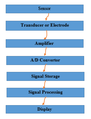
Each measurement system used in the medical field has different sections listed below. These sections are:
Sensors (used to measure physiological signals), converters or electrodes (used to convert the received signal into an electrical signal), amplifiers (responsible for amplifying weak signals), analog to digital converter (in this section analog signals are converted to digital), signal storage section (this section stores the signal that was converted to digital in the previous step), signal analysis (in this section operations and processing algorithms are performed on the digital signal), display (the last part of the measurement system is the display section because it is necessary to have an output for each measurement system, which is usually displayed on the display).
1. Respiratory Estimation System using Strain Gauge
This system is made up of different parts, which are: Strain Gauge Sensor, Differential Amplifier, Low-Pass Filter, Hysteresis Comparator, and Digital Counter.
Simulation of different parts of the circuit
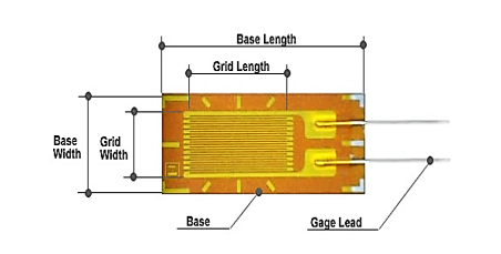
- Strain Gauge Sensor
A general definition for a strain gauge is that it is any device that measures surface deformation. A strain gauge is actually a sensor used to measure pressure. The electrical resistance changes when the sensor deforms [36]. The earliest type of strain gauge was invented by Ruge that this sensor consisted of a piece of cigarette paper to which a small wire was attached. Ruge later developed it with the help of his colleagues and it was patented [37].
Strain gauges are mainly divided into two categories: Bonded and Unbonded. bonded strain gauges are more commonly used. These strain gauges are made of metal foil. But the unbonded strain gauges are made of a very fine metal wire. Bonded or limited Strain gauge are known because these sensors must be attached to an elastic part [38].
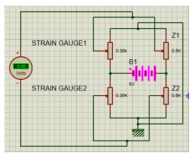
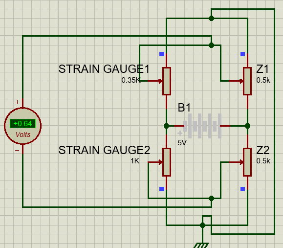
The best circuit to use the strain sensor is the Wheatstone Bridge circuit [39-45]. The Wheatstone Bridge is an electrical circuit consisting of four resistors, and when we want to use a strain gauge, we have to replace it with one of the resistors in the Wheatstone Bridge. The basis of bridge operation is the law of voltage distribution. The output of this bridge is amplified and recorded when it is measured.
There is no model for Strain Gauge in Proteus software, so a variable resistor was used instead. When breathing has done, the Strain Gauge resistance changes, causing the bridge to become unbalanced and generating voltage as the input to the next stage. The Strain Gauge used in this circuit is 350 ohms. We adjust the resistances in the other branches of the bridge using the variable resistors so that the bridge is in equilibrium. Here the value of these resistors is considered to be 500 ohms.
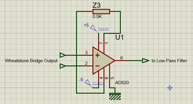
-Differential Amplifier
The AD620 chip is used for the amplifier. Among the features of this chip are: high accuracy, low cost, low noise, very high CMMR, high input impedance, low output impedance, gain or gain is in the range of 1 to 10,000, which requires only one resistor to adjust it.
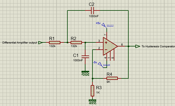
- Low Pass Filter
The LM741, which has eight pins, is used for the Low-Pass Filter. Pins number 2 and 3 are the inputs to the output of the previous stage (differential amplifier) is applied. Pins 4 and 7 are for powering the LM741, which connects to -5V and +5V. Figure 6 shows the simulated circuit of a Low-Pass Filter by Proteus software.
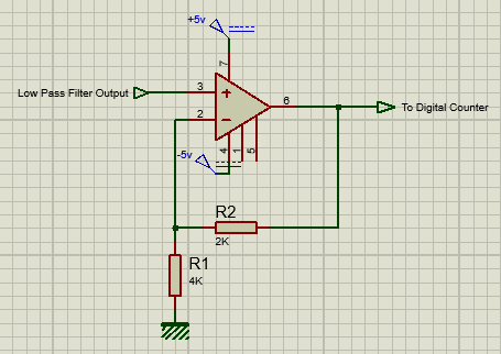
- Hysteresis Comparator
LM741 is also used in this part. Figure 7 shows the simulated circuit of the Hysteresis Comparator.
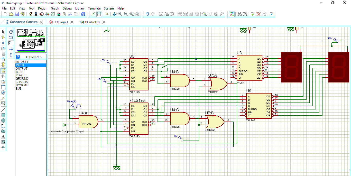
- Digital Counter
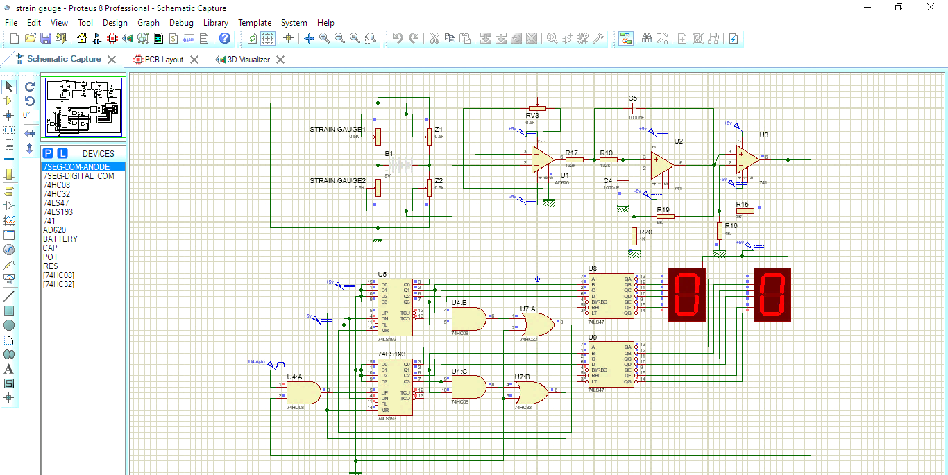
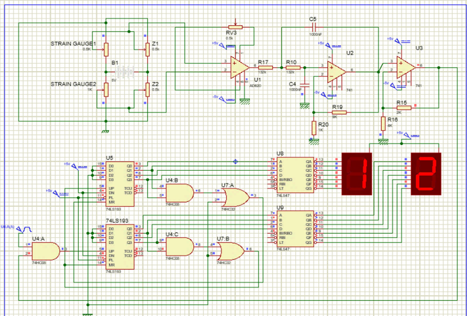
The Digital Counter consists of several parts. In the first stage, there is the 74LS193, which is a binary counter. Among the features of this chip are: high speed (counting frequency of 40 MHz), simultaneous counting, low power (average loss of 95 MHz), etc. [47]. The next step is the 74HC08 and 74HC32 chips. These chips belong to the AND s OR gates, respectively. The feature of these chips is that the operating temperature range is between -47 to 85 degrees Celsius, the maximum voltage required for power supply is 6 volts, and they have four gates. These chips have 14 pins that the pin number 7 is the ground and the pin number 14 is the power supply. The next step is the 74LS47 chip. This chip is commonly used in calculators, clocks, digital displays, etc. [48]. This chip is a BCD to Seven Segment converter. The maximum voltage required for this chip is 5 volts. It has 16 bases, which are 4 input pins (pins 1-2-6-7), 7 output pins (pins 9 to 15), 8 ground pins, and 16 power supplies. The last part of the digital counter is the seven-segment. There are two types of seven segments: common anode and common cathode. In this project, a common anode has been used. Each of the seven segments can display numbers from 0 to 9. To protect the seven segments, a resistor must be placed between the common base and the source or before each base. Finally, the simulated Digital Counter circuit is shown in Figure 8. This counter can count from 0 to 99. The complete circuit simulated by Proteus software is shown in Figures 9 and 10.
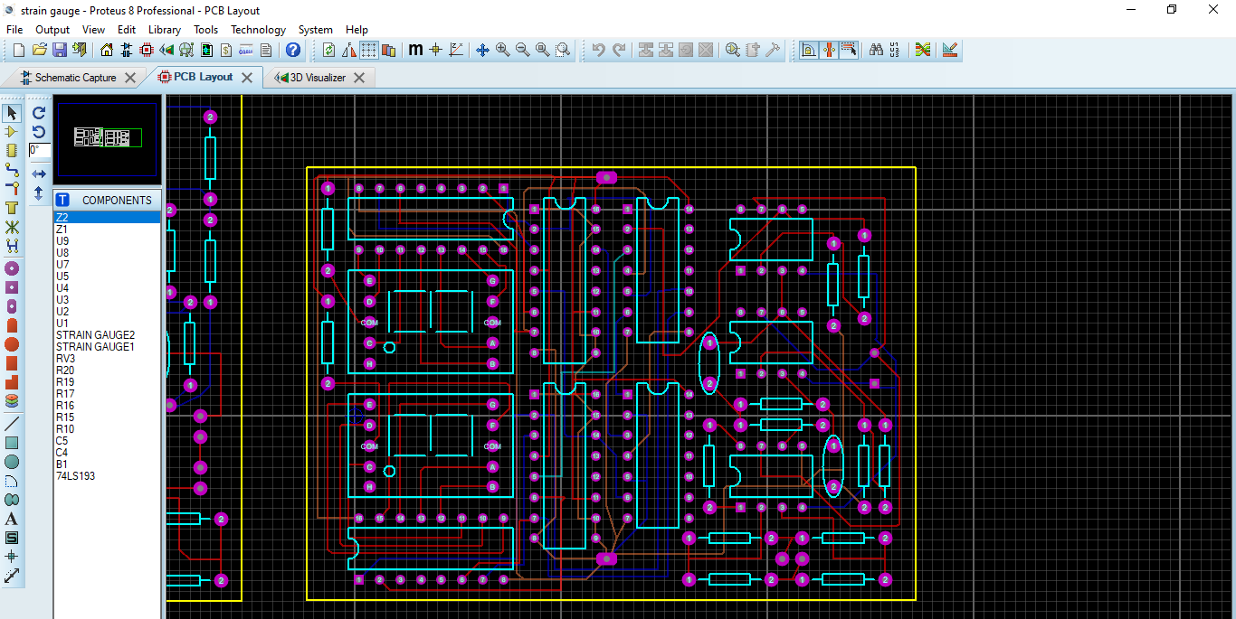
After completing the simulations and getting the desired results, the PCB circuit was designed. Figure 11 shows the designed PCB.

The next step after designing and simulating the circuits is to design and prepare the belt to which the system is connected. For this purpose, we must prepare a ring on which the sensors are placed. This ring must be flexible to affect the sensors if it is pulled or compressed. Steel can be used to make this ring. The point is that it should be as thin as possible to be flexible, so it is thick enough that the sensors can be placed on it. The made ring has a thickness of less than 1 mm, a radius of 23 cm, and a width of 1 cm. The next step is to attach the rubber band to both sides of the ring (Figure 13). This rubber fastens the ring on which the sensors rest on the chest.

2. Respiratory Estimation System using Induction Method
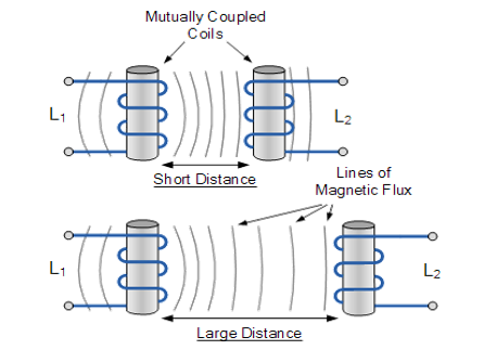
This system uses reciprocal induction in the windings. In this way, the excitation source is applied to the primary coil and this causes the induction voltage in the coil to be secondary, and this induced voltage changes with distance (Figure 14).
The coil that connects to the source is placed on the bed and the secondary coil is placed on the garment or blanket. The distance between these coils changes with each breath, and this causes a change in the voltage is induced. The secondary voltage is then applied to an ATMEGA16 and according to the program developed by the programming software for the micro, it is written that every time the voltage exceeds a certain limit, it indicates respiration, and finally the number of respirations is determined.
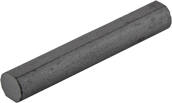
To make primary and secondary windings, experiments were first performed with coreless windings, but no significant voltage was induced in the secondary winding. Therefore, it was decided to use a ferrite core for the windings to amplify the inductive voltage. In electronics, ferrite is mostly used as the core. Due to its high magnetic permeability and low electrical conductivity, this property prevents the formation of eddy currents [50].
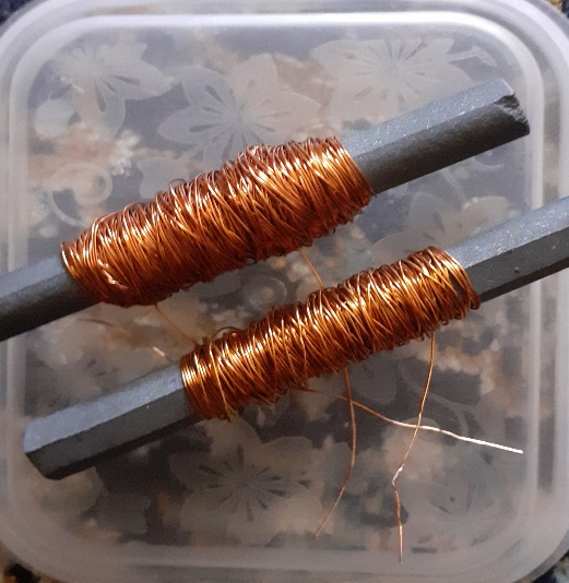
The wires used for winding should be as thin as possible so that they do not draw high currents and reduce the induced voltage. There are various types of copper wires available in the market, we selected copper wire with a thickness of 0.8 mm and coiled. Initially, 100 turns were wound for each coil, and the secondary induction voltage was approximately equal to 1 volt. To increase the inductive voltage, we must increase the number of turns of the windings. Therefore, in the next step the number of turns of the windings increased to 200 turns and the inductive voltage increased to 2 volts. In the next step, only the number of turns of one of the coils increased to 340 turns, and this coil was placed once as the primary coil and then as the secondary coil (Figure 16). When the number of turns of the primary winding was less than the number of turns of the secondary winding, the amount of induced voltage in the secondary winding increased. The inductive voltage was 3.670 volts when the coils were the shortest distance apart, and the inductive voltage reduced when the coils were spaced apart, reaching zero at the maximum distance of about 10 cm, and when they were close together again the inductive voltage increased.
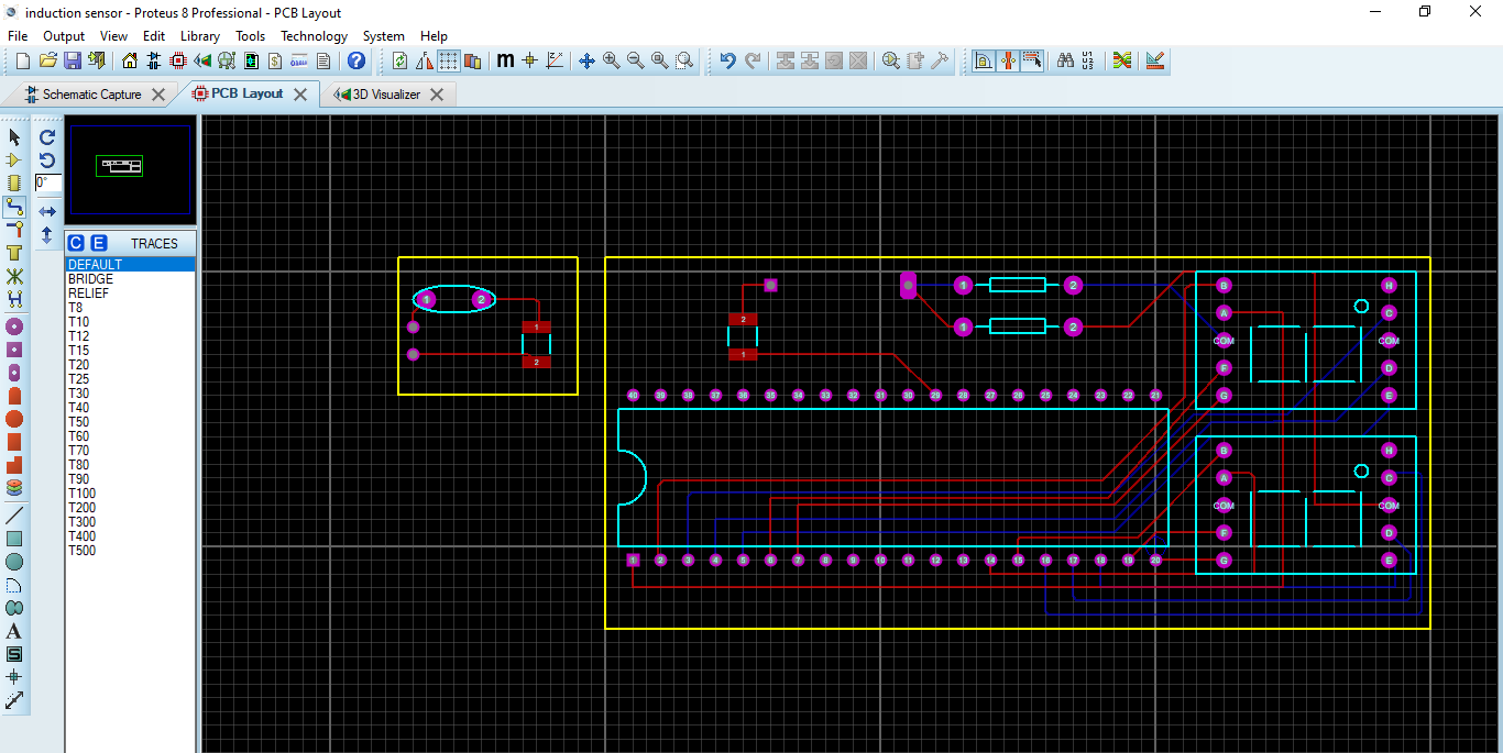
The complete simulated circuit of this system using Proteus software is shown in Figure 17 and the PCB designed in Figure 18.

Living conditions today have changed a lot and are different from before, so health care has become more important. A wide range of people, from infants to the elderly, need this care. With the advancement of science and knowledge, these cares are done using technology, because the use of old methods is associated with error. There are various methods and sensors for measuring the rate of respiration, whose task is to monitor the rate of respiration in order to prevent diseases and treatment. Sometimes it is necessary to use these monitoring devices at home or to have the device with the patient permanently until the end of the treatment period. Therefore, as far as possible, the designed devices should be devices with less bulk and weight and with the capability of remote monitoring and as non-invasive and wireless as possible, and they should be easy to use. Because respiratory disorders are one of the most common diseases in daily life, continuous monitoring of a patient's respiratory rate is importance. Respiratory disorders exist in children and even infants in addition to adults, so systems with the least amount of disturbance are required and can also be used at home because the infants are separated from their mothers and kept in the hospital for both of them problematic and annoying. Another advantage of such systems is that they are less expensive for families because they do not require hospitalization and also help the medical staff. Since continuous RR monitoring is very important for patients, infants, and the elderly, new technologies and monitoring systems are required on RR. The methods described in this article have advantages such as lower cost, Non-invasive, usability easy, higher accuracy, less space required, portability, and can be used at home. Interpretation of the obtained measurements does not require knowledge and expertise. It is comfortable to use and does not disturb the patient.
Dear Editorial Team, Clinical Medical Reviews and Reports. My experience with the journal was highly positive. The peer-review process was rigorous, constructive, and completed in a timely manner. The reviewers provided valuable comments that helped improve the quality and clarity of our manuscript. The editorial office was professional, responsive, and supportive throughout all stages of the publication process. Communication was clear and efficient, and any questions were addressed promptly. Overall, I found the journal to maintain high scientific standards and an excellent publication workflow. I would be pleased to consider submitting future work to this journal. Best wishes from, Elena Popa.

It was my pleasure to submit my testimonial concerning the Reviewer Board of our Scientific Journal “Brain and Neurological Disorders”. The Reviewers focused on some modifications and their contribution was helpful. The ladies of our Editorial Office were also supported my efforts. It was my honor to have such a co-operation and I am looking forward for more collaboration.

Dear Grace Pierce, Editorial Coordinator of Journal of Clinical Research and Reports, Thank you for the speedy and efficient peer review process. I appreciate the fact that your peer reviewers do not take months to respond like with some other journals. I would also like to thank the editorial office for responding quickly to my questions. It is an excellent journal. I plan to submit more manuscripts in the future. Best wishes from, Robert W. McGee

Dear Grace Pierce, Editorial Coordinator of Journal of Clinical Research and Reports, Working with you and your team on our recent publication in JCRR has been a truly wonderful and enjoyable experience. The responses were prompt, and the reviewers were patient, constructive, and highly professional. One reviewer in particular gave me the feeling that a professor was carefully reading and commenting on my coursework, which was deeply touching. The entire process was straightforward and hassle‑free, with no tedious online forms to complete. I highly recommend this journal. Best wishes from, DR Aibing Rao, Head of R&D

I Appreciate the Opportunity to Share my Experience with the Journal of Clinical Research and Reports. The peer review process was timely and constructive, and the feedback provided helped improve the quality of our manuscript. The editorial office was professional, responsive, and supportive throughout the process, ensuring smooth communication and efficient handling of the submission. Overall, it was a positive experience collaborating with your team.

Dear Mercy Grace, Editorial Coordinator of Obstetrics Gynecology and Reproductive Sciences, We would like to express our gratitude for your help at all stages of publishing and editing the article. The editors of the magazine answer all the necessary questions and help at every stage. We will definitely continue to cooperate and publish other works in the Obstetrics Gynecology and Reproductive Sciences! Best wishes from, Alla Konstantinovna Politova,