Research Article | DOI: https://doi.org/10.31579/2641-0419/144
*Corresponding Author: Macian Canto Estefanía, Medical Equipment Department 2, Combiomed Digital Medical Technology, Cuba
Citation: Macian Canto Estefanía and Martínez Varona Israel., (2021) Design of a Portable Pulse Oximeter. J. Clinical Cardiology and Cardiovascular Interventions, 4(7); Doi:10.31579/2641-0419/144
Copyright: © 2021 Macian Canto Estefanía, This is an open-access article distributed under the terms of the Creative Commons Attribution License, which permits unrestricted use, distribution, and reproduction in any medium, provided the original author and source are credited.
Received: 11 February 2021 | Accepted: 17 March 2021 | Published: 25 March 2021
Keywords: photodetector; hemoglobin; oximetry; oxygen saturation
Oximetry is a technique that allows the evaluation of oxygen levels in the blood in patients who suffer from a pulmonary disorder or present a respiratory pathology. The main objective of this research is the design of a portable pulse oximeter, which corrects the problems of the oximeter previously developed by the ICID, due to the module used at defined low perfusion levels (modulation index of 0.4% and lower), It had difficulties to synchronize with the patient's pulses and for severe low perfusion conditions (signals with a modulation index of 0.2% and less), the module did not operate.
With respect to past designs, this project incorporates an oximetry module produced by recognized companies in this field, thus eradicating the deficiencies of the previous models. The components were updated, using, for example, an LCD screen, a DC / DC converter, optocouplers and the MSP430F2618 microcontroller which is very suitable for this design, as it contains sufficient resources in data and program memory.
The design of the schematics of each circuit that makes up the oximeter is carried out. As well as the development of firmware programming, based on the graphic design of the algorithms of the main functions of the equipment.
The essential elements of the pulse oximeter design were explained, highlighting its main functions, the benefits it will offer, as well as the algorithms and firmware that define the functionality of the equipment.
Acute respiratory infections are considered among the leading causes of morbidity in the world, with emphasis on patients of child age, in addition to greater control in the general population, which requires greater medical attention. Most of the consultations and admissions in this medical specialty, fall precisely on these infections, which are among the first five causes of death in the world and there are regions where it can increase due to the appearance of certain predisposing factors [1].
For this reason, it is necessary to evaluate the oxygen levels in the blood in patients who suffer from a lung disorder or present a respiratory pathology, because if this level is low, the cells of your body may have difficulties to adequately comply with their requirements functions.
With the development achieved by pulse oximetry, oxygenation monitoring experienced revolutionary progress, allowing the evaluation of peripheral oxygen saturation (SpO2) in a continuous, reliable and non-invasive way. Pulse oximetry is a technology capable of measuring oxyhemoglobin saturation (HbO2) based on the combination of two principles: plethysmography and spectrophotometry. With the first principle, a pulsatile volume change is identified in the analyzed region and, assuming that this pulsatile component corresponds to arterial blood, absorption spectrophotometry is used to measure the oxygen saturation of the hemoglobin of said sector [2].
The measurement of oxyhemoglobin saturation in the blood is based on the fact that the arterial blood flow is pulsatile and in the rest of the fluids and tissues it is not. In this way, the pulsation of arterial blood modulates the light that passes through it, while it does not occur in the other fluids and tissues, where a constant absorption is maintained. At the measurement site, it is assumed that the pulsatile arterial component (AC) (Figure 1) varies the absorbed light by increasing the length of the optical path, modifying the relative portions of HbO2 and reduced hemoglobin (HbR) [3]

Figure 1: Absorption of light in the finger
The light absorption spectrum of HbO2 and HbR, oscillate at wavelengths that are between 640 nm and 940 nm, whose differences are maximum in the red and near infrared region of the spectrum.
The general operation of the sensor (Figure 2) is based on the use of a light source with the two mentioned wavelengths, which is applied to an area of the body, thin enough to allow light to pass through the blood vessels. and is captured by a photodetector [2]. It is usually applied to the index finger of the patient, although in the cases of children or neonates other parts of the body are used, such as the feet.
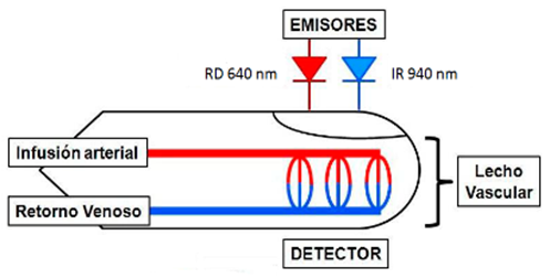
Figura 2: Esquema de medición de HbO2 y HbR.
Materials and methods:
Figure 3 shows the block diagram of the portable pulse oximeter design for blood oxygen saturation measurement. This diagram shows the sensor connected to the oximetry module that is responsible for acquiring the signal, allowing the measurement of SpO2 in any type of patient (adults, children and neonates).

Figure 3: Block diagram of the oximeter
It is proposed that, to obtain the signal, the reusable SpO2 sensor U400-A was used, manufactured by UNIMED (Figure 4A), which works with an LED of wavelength between 660nm / 940nm, values related to functional hemoglobins of the blood.
The values acquired by the sensor were processed by the SpO2 module FM-QSZ-I (Figure 4B) produced by Shenzhen Fitfaith Technology Co., Ltd. This module allows obtaining parameters such as SpO2 oxygen saturation, pulse and plethysmographic wave. . For the realization of the software (firmware) of the oximeter, the microcontroller MSP430F2618, (figure 4C) from Texas Instruments was used. Finally, the data will be displayed on the 2.4 '' diagonal LCD KWH024Q07-F01 (Figure 4D), manufactured by Formike Electronic Co., Ltd.
The Altium Designer 15 program was used for the design of the schematic circuit diagrams and the IDE IAR Embedded Workbench 7 was used for the programming of the microcontroller.

Figure 4: Main materials to be used for the design of the oximeter
Results and Discussion:
• Main board of the oximeter
The Main Board (Figure 5) is composed mainly of the microcontroller and the two power inputs: an external 5V source and a battery; and the peripherals that the μC controls: such as a matrix keyboard to access the menu options, the LCD that includes the ILI9341 controller and a horn for the equipment alarm; as well as a 3.3 V power supply that allows to energize the MSP430F2618 microcontroller using the NCP1117 regulator to obtain this voltage value and whose fixed configuration is shown in Figure 6.

Figure 5: Main Board
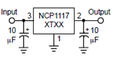
Figure 6: Speaker Configuration
Both power inputs have a fuse connected to the output of their connectors (P1 and P2) that melts when the current intensity exceeds, due to a short circuit or an excess load, a certain value that could endanger the equipment. A zener diode was connected in series with the fuses to prevent the current from passing in the opposite direction.
• Peripherals
To operate the equipment, a matrix keyboard with five keys is used, connected to the first four pins of the P1 port of the MSP430. In the matrix keyboard configuration, the keys deliver 0 V as long as the button is not pressed and 3.3 V when the button is pressed. A 10 kΩ resistor is connected to this configuration, limiting the current to 0.33 mA.
For the configuration of the horn (Figure 7) in the three volumes that the equipment will have enabled, a transistor was used as a switch, which will have a specific voltage at the output of its collector according to the volume that is selected.

Figure 7: Speaker Configuration
To connect the LCD screen, the first eight pins of the P4 port of the MSP430 were used for the data bus and the first four pins of the P3 port, including the P3.7 pin for the screen configuration. Figure 8 shows the LCD connector and the connector pinout, which includes the ILI9341 controller pins.
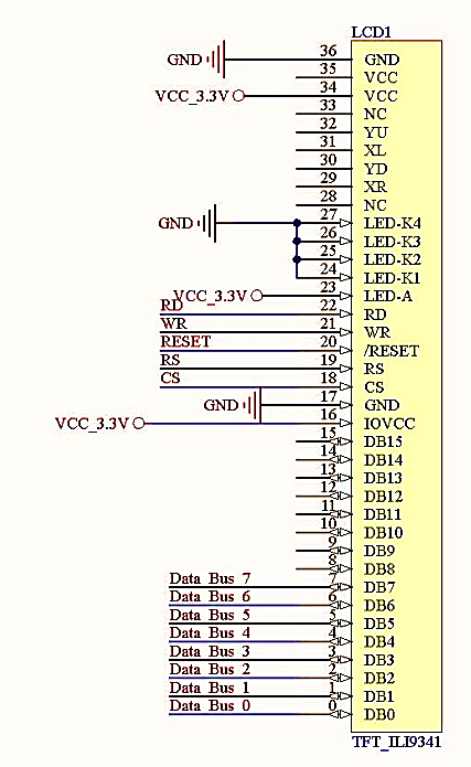
Figura 8: Distribución de pines del LCD
• Interface and Isolation Block
The main objective of the interface and isolation block (figure 9) is to guarantee the protection of the patient by creating an isolation between the patient and the equipment. Through a five-pin connector (J3) the connection with the Main Board is achieved. At the Vcc input of this connector there is an NPN transistor 2N3904, in common emitter configuration, which allows current to pass only when the Enable pin is set to “1”.
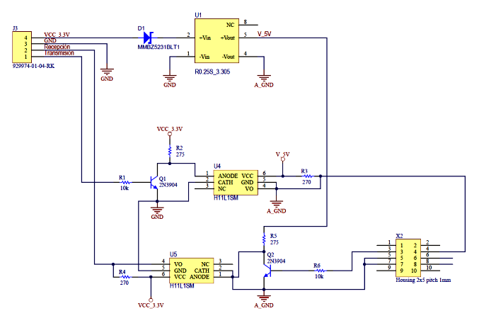
Figure 9: Interface block and isolation
The DC / DC converter R0_25S_3.305 raises the voltage of 3.3 V, at the output of the regulator of the power supply unit, up to 5 V and maintains this voltage stable.
H11L1M optocouplers were used to allow the communication of the SpO2 oximetry module with the microcontroller, without the need for an electrical connection. The configuration of the optocouplers was carried out to guarantee the isolation of the patient with the equipment and so that the reception had the adequate voltage to be carried out. The transistors were used as switches to guarantee only the passage of the required voltages.
The configuration at the input of the photodiode was designed according to the configuration recommended by the manufacturer of the 2N3904 transistor, taking into account that the values of Rb and Rc were valid so that the photodiode voltage was less than 1.2 V, which is the maximum value of allowed voltage.
• Microcontroller firmware
After analyzing all the functionalities that the oximetry module presents, we proceeded to develop the programming, based on the algorithm of the main functions presented in a flow diagram, so that the firmware was capable of executing all the module's features.
In figure 10, the main program flow diagram is shown, where the variables are defined and the registers and ports of the microcontroller are configured. Specifically, the program polls if the equipment is already on and once it is activated it displays the information on the screen, analyzing the sound to be generated, as long as there is no interruption due to pressing a key.

Figure 10: Main Program Flow Chart
The data received through the reception subroutine, due to the interruption of the RS232 port, is stored in a buffer that is analyzed in the Receive function, whose function is shown in the flow diagram of Figure 11. These data are received by 5-byte packets of information and the module sends 60 packets of data per second.

Figura 11: Diagrama de flujo de Recibir (), donde se analizan los datos recibidos
This function extracts the data received from the storage buffer and then asks for the Byte_a_read variable to analyze the information of each byte in its order. When this variable is equal to zero, the first byte of the data packet is parsed.
The 5-byte analysis is explained below, based on the flow diagrams presented in the graphic combination of figure 12.
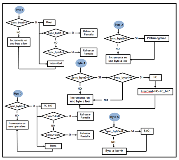
Figure 12: Graphical combination of the five-byte flow diagrams
Byte 1: The first bit of each byte that is analyzed is the synchronization bit, since if it does not have the value defined in the communication protocol, the other bits that make up the byte may have erroneous information and, in this case, it must be equal to one. If it corresponds to this value, the next bit that contains the information on whether there is a beep or not is analyzed. The next two bits contain information about two of the errors that can occur in the measurement (searching too long and sensor down). The last four bits report the perfusion index (Intensity).
After analyzing the 8 bits of the first byte, the value of Byte_to_read is increased and the second byte is analyzed. Similarly, if the synchronization bit is equal to zero, the remaining bits are not analyzed and the next byte of the packet is skipped.
Byte 2: In the flow diagram where the second byte of the packet is analyzed, again the synchronization bit must be equal to zero, so that the remaining 7 bits can be analyzed, which contain the information to graph the plethysmographic curve. the value of Byte_to_read is increased by one and the next byte is analyzed, considering that the synchronization bit is equal to one.
Byte 3: The analysis process of this byte is the same as the case of the second byte, shown in the corresponding flow diagram of figure 12.
In this case, after verifying that the condition set for the synchronization bit is met, the next bit containing the pulse frequency value (FC_bit7) is analyzed. Next, the next two bits are analyzed, which report on another two of the errors that can occur in the measurement (error in the sensor, searching for a pulse) and finally, the next four bits give the information for the bar graph. At the end, Byte_to_read is increased, and the analysis of the fourth byte begins.
Byte 4: In the initial analysis of the synchronization bit, it is analyzed if the synchronization bit of the third and fourth byte has a value of zero. If this is true, the information is extracted from the remaining 7 bits of the fourth byte, which contain part of the information on the pulse frequency (FC) value. Subsequently, FC and FC_bit7 are added to obtain all the information of the pulse frequency value. At the end, the value of Byte_a_read is increased again and the fifth byte is analyzed.
Byte 5: The analysis of the last byte of the data packet finally provides us with the value of the oxygen saturation SpO2.
• Menu Management
An important aspect of programming is the operation of the menu with the keyboard. Below are the flowcharts for this part of firmware programming (figure 13). For the management and control of the main menu and the submenus, the variable Current_Position was created, which indicates the position in which the menu cursor is located, defined with an identifier.
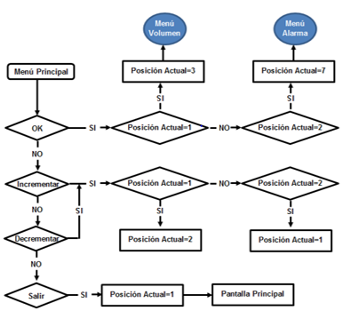
Figure 13: Main Menu flow chart.
This operation is carried out as follows: if you are in the main screen and press the Menu / OK key, you enter the main menu, where it is positioned (by default) in the first option (Volume). If the same key is pressed again, Current_Position is set to 3 and the Volume submenu is entered. When Current_Position is equal to 2, it indicates the Alarm option, so if Menu / OK is pressed, the Alarm submenu is entered.
If the increase or decrease keys are pressed, the value of the selected variable is increased or decreased respectively. In either of the two options, if the exit key is pressed, Current_Position takes its initial value (Current_Position = 1) and exits to the main screen.
In the case of the Volume submenu, whose flow diagram is shown in Figure 21, when entering this submenu the variable Current_Position is placed in position 3 (High Volume). From this position and, depending on the pressure on the key, the program allows you to go from High Volume, to Medium Volume, Low Volume and Silence.
In the Alarm submenu, the value of the alarm level is configured, which should begin to emit the visual and audible warning, whose default value is 90.
The Menu / OK key simply does not have a recognizable function within this submenu and if Exit is pressed, the Current_Position variable is set to 2, which corresponds to the Alarm option in the main menu.
In this menu, the most important keys are decrease and increase, since the Alarm_Level value varies with these keys. The increase must reach the value 95: higher than this, an error sign (Limit Exceeded) will appear on the screen, remaining at 95. With the decrease key, something similar happens, but this time the value is decreased by one to 80. If it continues to decrease after this value, the same error sign will be printed on the screen and it will remain at 80.
A study of the theoretical foundations of pulse oximetry was carried out, covering the biological variables that intervene in the operation of the oximeter and that, in general, lead to obtaining oxygen saturation in the blood.
The design of the pulse oximeter was explained, considering its analog design, starting with the preparation of the general block diagram of the oximeter, presenting the different main components and completing the design of the Main Board and the Interface and Isolation Block.
In the same way, the algorithms and firmware programming were developed, based on its functionalities.
Our thanks to all who, in one way or another, contributed to the outcome of this project.
Conflicts of Interest
The authors declare that there are no financial interests or any type of conflict of interest.
Dear Editorial Team, Clinical Medical Reviews and Reports. My experience with the journal was highly positive. The peer-review process was rigorous, constructive, and completed in a timely manner. The reviewers provided valuable comments that helped improve the quality and clarity of our manuscript. The editorial office was professional, responsive, and supportive throughout all stages of the publication process. Communication was clear and efficient, and any questions were addressed promptly. Overall, I found the journal to maintain high scientific standards and an excellent publication workflow. I would be pleased to consider submitting future work to this journal. Best wishes from, Elena Popa.

It was my pleasure to submit my testimonial concerning the Reviewer Board of our Scientific Journal “Brain and Neurological Disorders”. The Reviewers focused on some modifications and their contribution was helpful. The ladies of our Editorial Office were also supported my efforts. It was my honor to have such a co-operation and I am looking forward for more collaboration.

Dear Grace Pierce, Editorial Coordinator of Journal of Clinical Research and Reports, Thank you for the speedy and efficient peer review process. I appreciate the fact that your peer reviewers do not take months to respond like with some other journals. I would also like to thank the editorial office for responding quickly to my questions. It is an excellent journal. I plan to submit more manuscripts in the future. Best wishes from, Robert W. McGee

Dear Grace Pierce, Editorial Coordinator of Journal of Clinical Research and Reports, Working with you and your team on our recent publication in JCRR has been a truly wonderful and enjoyable experience. The responses were prompt, and the reviewers were patient, constructive, and highly professional. One reviewer in particular gave me the feeling that a professor was carefully reading and commenting on my coursework, which was deeply touching. The entire process was straightforward and hassle‑free, with no tedious online forms to complete. I highly recommend this journal. Best wishes from, DR Aibing Rao, Head of R&D

I Appreciate the Opportunity to Share my Experience with the Journal of Clinical Research and Reports. The peer review process was timely and constructive, and the feedback provided helped improve the quality of our manuscript. The editorial office was professional, responsive, and supportive throughout the process, ensuring smooth communication and efficient handling of the submission. Overall, it was a positive experience collaborating with your team.

Dear Mercy Grace, Editorial Coordinator of Obstetrics Gynecology and Reproductive Sciences, We would like to express our gratitude for your help at all stages of publishing and editing the article. The editors of the magazine answer all the necessary questions and help at every stage. We will definitely continue to cooperate and publish other works in the Obstetrics Gynecology and Reproductive Sciences! Best wishes from, Alla Konstantinovna Politova,