Review Article | DOI: https://doi.org/10.31579/2694-0248/044
Institute for Advanced Engineering, 175-28, Goan-ro 51 beon-gil, Baegam-myeon, Cheoin-gu, Yongin-si, Gyeonggi-do, 17180, Korea.
*Corresponding Author: Dongchan Lee, Institute for Advanced Engineering, 175-28, Goan-ro 51 beon-gil, Baegam-myeon, Cheoin-gu, Yongin-si, Gyeonggi-do, 17180, Korea.
Citation: Dongchan Lee. (2023), Characteristics of the Stress-Strain Curve of Auxetic Structures for the Monitoring and Analysis of Human Body Bio-Signal, J Clinical Orthopaedics and Trauma Care, 5(5); DOI: 10.31579/2694-0248/044
Copyright: © 2023, Dongchan Lee. This is an open access article distributed under the Creative Commons Attribution License, which permits unrestricted use, distribution, and reproduction in any medium, provided the original work is properly cited.
Received: 21 October 2023 | Accepted: 15 November 2023 | Published: 29 November 2023
Keywords: auxetic structure; cross chiral structure; variable stiffness; musculoskeletal assistive structure
The tendons that connect muscle to the bone under human physical activity show that they get fatter and thinner when stretched and contracted, and exhibit unusual auxetic behaviors. A tendon is a tough, high-tensile-strength band of dense fibrous connective tissue. In transmitting the mechanical forces of muscle contraction to the skeletal system, the tendon behaviors in abrupt movements such as jumping are essential for positioning as well as energy absorption. But they are also prone to damage when injuries occur. For decreasing the damage caused by the load-transmitted burden of tendons, the auxetic musculoskeletal assistive structure is proposed in the visco-elastic form with a fitting ability to simultaneously contract and expand in two perpendicular directions when the body motion occurs. To design a macro-auxetic structure with elastic flexibilities in the musculoskeletal assistive structure, it is important to develop an auxetic unit cell with the variable stiffness. Auxetic structures play key roles in assisting human motion. Periodic cellular structures used in the auxetic structures are first considered in the field of lightweight construction due to their high specific stiffness, damping, and energy-absorbing properties. In the periodic unit cell, the structural performance may be influenced by the strut angle. The collapse of the CCS (Cross Chiral Structure) structure occurs at around 20 degrees of the strut angle. Under 10 degrees, the structure possesses a linear behavior. When a more obvious inflection range exists, clearer changes in strength and flexibility can be observed and the external force absorption is expected to be excellent. Over 30 degrees, it is like a solid block from the beginning of external force and does not show the structural characteristics of CCS.
Tendons in the skeletal movement of human body mainly composed of collagen fibers are viscoelastic structures that permit force transfer from muscle to bone. They are essential for positioning as well as energy storage for abrupt movements, such as jumping. Nevertheless, some severe injuries, such as Achilles tendinopathies commonly occurring in athletes, cause irreparable damage to tendons. To protect tendons from such damage, understanding their viscoelastic behavior is very important. Tendons display a stretched and a crimped structure with and without a load, respectively. In detail, stretching a tendon causes bundles of fibers, called fascicles, to slide against each other, and it eventually returns to their original shape when an external force is released. Stretching beyond this range, called a yield stress, results in permanent deformation [1, 2].
Auxetic musculoskeletal assistive structures have been proposed as a solution to minimize the load-transmitted burden to a tendon. The structures worn on a human body can simultaneously contract and expand in two perpendicular directions due to their negative Poisson’s ratio as the body motion occurs. This permits the structures to conform to the contours of the body with the best comfortable fit. To fabricate an auxetic structure with elastic flexibilities in macro-size for a musculoskeletal assistive device, a few attempts to study an auxetic unit cell with the adjustability of stiffness have been made. For example, periodic cellular patterns for the auxetic unit cell are considered in the field of lightweight construction due to their high specific stiffness, damping, and energy-absorbing properties [3]. Their critical design, materials, and processing methods for the optimal patch to target specific pathology in biomechanics are outlined in Chansoria et al. [4]. An organic review on various biological systems with sophisticated architectures for impact resistance and energy absorption is provided. Furthermore, their dynamic behaviors related to designs and underlying mechanisms are discussed. For instance, results demonstrate that representative bio-inspired structures exhibiting beyond 60 J/g for specific energy absorptions can be used for excellent impact protection structures [5]. Such mechanical properties can be controlled by appropriately choosing the pattern of the underlying unit cell with a negative Poisson’s ratio [6~8]. Even several 3D auxetic cellular structures have been developed by adapting simple 2D structures into 3D re-entrant hexagon cellular structures [9-11].
In this paper, auxetic structures with various combinations of materials and components are investigated for the variable stiffness and comfortability of potential applications in body protection and support. An auxetic material is a class of meta-materials that exhibit a negative Poisson’s Ratio. It has been known for over a hundred years but has only gained attention in recent decades. It can be a single molecule, but more often consists of an engineered material with a particular structure on the macroscopic level. Auxetic structures can be created by using flexure hinge-like or spring-like features that change their shapes (thickness, width, height) when a force is applied to them. If an axial tensile force is given, the hinge-like structures extend, causing lateral expansion. If a compressive force is applied, the hinge-like structures fold even further, causing lateral contraction. Thus, man-made auxetic materials may be used to manufacture adaptive clothes with variable stiffness. Adaptive clothes need auxetic material patches with variable stiffness, which contain the auxetic cell shown in Figure 1. In order to achieve bending behavior with a structure of variable stiffness, the intermediate layer must be constructed in the form of a meta-structure. If a constant voltage is applied depending on the amount of load voltage, due to the form of a meta-structure consisting of cells of the same structure as a spring, it is compressed into electromagnetic properties that occur at the electrode layer, and according to the fluctuation of the constant voltage changes in the cells of the meta-structure occurs resulting in spring-like variable stiffness, thus bending deformations will appear above and below a certain voltage. Finite element analyses and experiments are conducted to evaluate the performance and effectiveness of the auxetic structures. In the future, the possibility of making pad structures thinner and lighter will be examined through an optimization process using geometric dimensions. The development of this kind of structure makes it possible for soft robots to adjust their stiffness levels in real time during the operation. Soft robots can perform sophisticated and precise movements for tasks requiring fine manipulation while keeping the wearers safe. These advancements will broaden the scope of soft robotics applications and contribute to the development of more capable and user-friendly robotic systems. This is particularly beneficial in applications involving human-robot interaction or tasks related to collaborative manufacturing, assistive devices, and healthcare robotics.
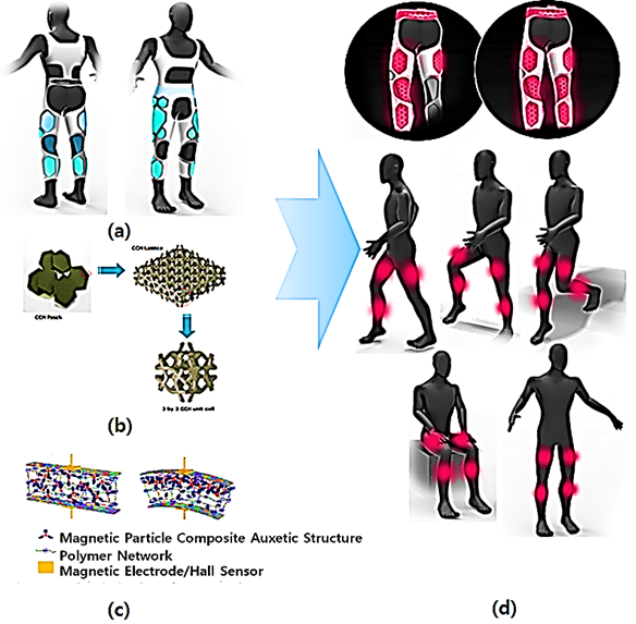
Figure 1: Auxetic musculoskeletal assistive structure with variable stiffness; (a) Concept of Soft garment; (b) 3D Auxetic structure with adjustable stiffness and unit cell; (c) Electro-Active deformation of 3D Auxetic structure for motion intention.; (d) Muscular activation support system for daily life
Various designs were generated and investigated based on criteria such as performance, comfort, and manufacturability. Auxetic materials are a class of meta-materials on the cell geometry which exhibit a negative Poisson’s Ratio. The structural characteristics of auxetic material depend on the cell geometry [12-15].
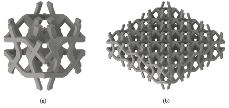
Figure 2: 3D models of cross chiral structure. (a) Unit cell of cross chiral structure; (b) 3 x 3 x 1 lattice of cross chiral structure
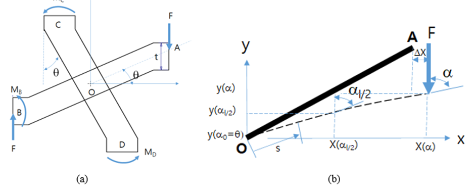
Figure 3: Schematics for CCS (Cross Chiral Structure) unit; (a) Strut Configurations of CCS; (b) Bending deformation of strut
Figure. 2 shows a unit cell structure and 3x3x1 lattice structure, which composed of three-unit cells in row and column, respectively, for the investigation of CCS. The cross-chiral auxetic structure has a symmetrical geometry, as shown in Figure. 3. After rotation in the out-of-plane direction, this serial and parallel configurations of 2D structure can be readily patterned into a 3D structure, CCS, as shown in Figure 3. The CCS has a symmetrical geometry and can readily be patterned into a 3D structure with rotation in or out of a plane. Figure. 3 shows a structural schematic model in a plane view. The representative unit of CCS is determined by four primary geometrical parameters: length of the strut L, the tilt angle of the strut , strut's cross-section in-plane thickness t and width w, as shown in Figure 3. In this study, it is supposed that the cross-sectional shape of struts in CCS is square, so it can be assumed that t=w.
Three configurations are designed for the following compression experiments in the z-direction. For each design, the cubic unit cells are arranged periodically to form 3D lattice samples with 3 × 3 × 1 unit cells. The tilt angle of the strut varies from 10 to 30 with the size of the unit cell constant. The models described above are chosen because the geometry of CCS can be varied systematically using a single parameter, , which facilitates the analysis of the deformation mechanisms of the auxetic materials. Meanwhile, the size of each model needs to meet the requirements for fabrication and experiments. The force analysis of the representative unit at the top or bottom layers is shown in Figure 3. The end-point A is the free end, which is only contacted with the hard striker. But, due to the symmetry of the structure, constraints at the end-points B, C, and D are much stronger because of the rigid connection with other units. As a result, the main deformation occurs in strut-OA while slight deformation is observed in other struts. Therefore, the deformation of the struts-OB, OC, and OD can be neglected, and strut-OA is simplified to a cantilever beam where the origin O is fixed in this model.
The bending moment and axial stress at origin O can be expressed as,

The model regarding large deflection takes nonlinear dimensional change into consideration and it is expected to be more accurate in calculating the value of stress in a typical position. Before reaching the plastic yield stress, the strut is subjected to large deflection upon loading, which could affect the stress distribution, as shown in Figure 3-b. The model regarding large deflection takes nonlinear dimensional change into consideration and it is expected to be more accurate in calculating the value of stress in a typical position. Additionally, the perfectly plastic beam is also used and several assumptions are adopted for theoretical analysis: the large deformation is analyzed in the elastic section of the material and the process will not be considered that the failure occurs at the surface first and then extends across the entire section when the strut starts to yield.
In Figure 3-(b), a curvilinear coordinate S, with origin O, is used to define the position of the bending member. Neglecting the change in length of OA due to axial compression. According to the Euler-Bernoulli theorem for beam bending, the differential equation of the deflection curve is,

where I is second moment inertia of the cross-section and  ,
,  is the bending angle of a general point along a deformed member between the tangent of the shape of the inclined member and the loading direction, Δ
 is the maximum lateral displacement before the strut fails, s and are the distances of a general point along the curvilinear coordinate and along the horizontal direction from origin O, respectively. Considering the relationship between the O-xy and O-s coordinate systems, the following geometrical relationships could be readily obtained,

Differentiating Eq. (2) with respect to s and combining Eq. (3), we obtain,

Using Eq. (4), the following equation can be yield,
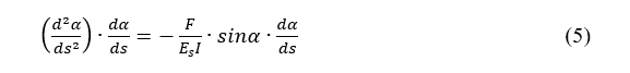
Eq. (5) may be integrated once to yield,

where the boundary conditions is,

and then

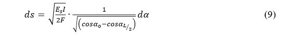
It can be seen form Figure 3-(b) that  is positive, solving for ds gives,
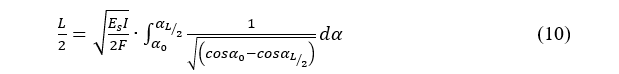
Performing one more integration of Eq. (9) yields,
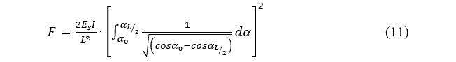
From eq. (10), the force F can be expressed as,
For these bending-dominated cell structures, the yield stress is obtained by setting the moment equal to the collapse moment in the critical struts. If the fully plastic behavior for a perfectly plastic beam under combined bending moment and extensional stress can be estimated, the loading conditions may be predicted for the bending angle of a general point along a deformed member between the tangent of the shape of the inclined member and the loading direction.
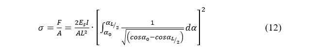
Using Eqs. (3) and (9), the horizontal projected distance x() of a general point (x, y) on the strut-OA along the x-axis and the vertical projected distance y( ) of the general point (x, y) along the y-axis can be estimated. From eq. (12) on the effective area of unit cell strut(A), the basic dimensions of geometries may be estimated below the fracture strength of struts of unit cell of cross chiral structure.
Auxetic cells made of polyurethane in Table 1 exhibit a negative Poisson’s Ratio and their auxetic characteristics depend on the cell’s geometric parameters. For the auxetic structure with variable stiffness, a 3D printer (FORMIGA P110, EOS) was used to build specimens using a material called PEBA2301. The dimension size of auxetic blocks is 30 (mm) x 30 (mm) x 10 (mm) shown in Figure. 4-(a) which have the different tilting angle of unit cell for the experiments and the investigation of their structural characteristics. The fabricated specimens are doubled in width and height on the fixed thickness. Compression strength is the maximum stress that a material can withstand while being compressed before failing or breaking as shown in Figure. 4-(b). It is an important mechanical property of auxetic materials. A universal testing machine (QM100SE, QMSYS) was used to measure the mechanical properties of the 3D structural specimens. The set-up for the experiment was arranged based on a standard manual that specifies the sample preparation, fixturing, gauge length, analysis, etc. The specimen was placed in the machine between the grips and an extensometer, which records the change in gauge length during the test. If an extensometer is not installed, the machine itself can record the displacement between its crossheads on which the specimen is held. Once the machine starts, it begins to apply an increasing load on the specimen. The payload can be applied up to 40kgf as shown in Figure. 4-(c).
| Characteristics | Unit | Polyurathane (Semiflex) |
| Density | kg/m3 | 1200 |
| Young’s Modulus | MPa | 15.30-25.82 |
| Shear Modulus | MPa | 3.27-8.38 |
| Poisson’s Ratio | - | 0.48 |
| Tensile Strength | MPa | 23 |
Table 1: Material properties of auxetic cell
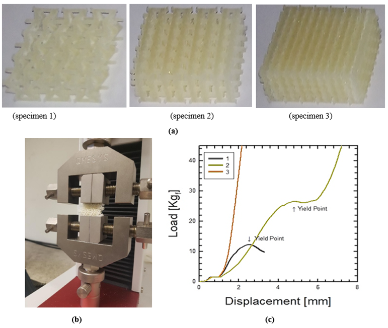
Figure 4: Test specimens and machine for the structural properties of an auxetic unit cell; (a) Auxetic structure specimens; (b) Compression test using universal tensile machine; (c) Force-displacement curve of specimen 1, 2, and 3
Figure. 4 shows various auxetic structure specimens with the amounts of porosities which is not filled with the unit cells. Sample 1, 2 and 3 are CCS (cross-chiral structure) structure with the top and bottom plates that is to protect the warping behaviors of auxetic cells. Each sample has some porosities, respectively: Sample 1: 75% porosity ratio, Sample 2: 50% porosity ratio, Sample 3: 25% porosity ratio. Under compression tests, the mechanical characteristics of samples are different to the porosity ratio of CCH structure. As the CCH structure becomes denser, the behavior of CCH structure becomes stiffener. In this paper, sample 2 is selected as the valid prototype for the soft auxetic structure with variable stiffness [5-8]. Figure. 5 shows the stress-strain curve for sample 2 with respect to the various angular variables (θ) of the CCS bridge and Figure. 6 shows the displacement contour with respect to the angular variables. As the lower angle is applied, more resistance capacity and faster inflection are observed. The collapse of the CCS structure occurs at around 20 degrees of the strut angle θ. Under 10 degrees, the structure possesses a linear behavior. When a more obvious inflection range exists, clearer changes in strength and flexibility can be observed and the external force absorption is expected to be excellent. Over 30 degrees, it is similar to a solid block from the beginning of external force and does not show the structural characteristics of CCS.
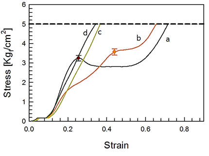
Figure 5: Stress-strain curve of CCS for different strut angle θ (a: 10 degrees, b: 20 degrees, c:. 30 degrees, d: 40 degrees) UTM results are given by solid lines; symbols denote yield points; the chain line represent our reference value, 5.
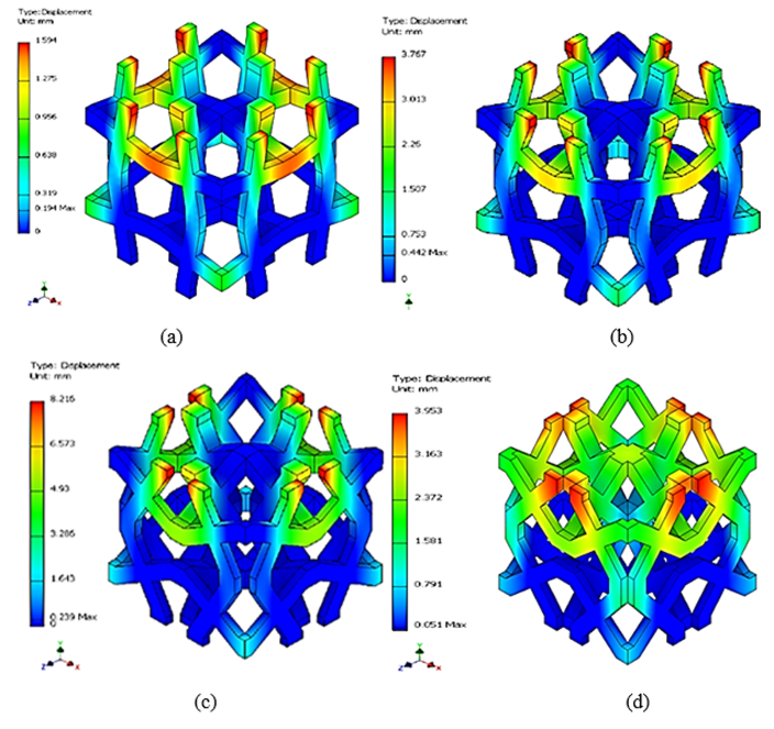
Figure 6: Deformation contour of CCS unit for different strut angle θ; (a) 10 degrees; (b) 20 degrees; (c) 30 degrees; (d) 40 degrees
Using the auxetic sample 2 of 3x3x1 CCS structure, the stress-strain curve, and strain coefficient are shown in Figure 7 and 8 for the compression ratio (compressibility) percentages (a. 0%, b. 20%, c. 30%, d. 40%). Those figures show the average values obtained from five experiments for each sample, in which the solid line shows the experimental value of the universal testing machine and the symbol depicts the inflection point on the structural change or analogical yielding point (5 kgf/cm2). Except for the analogical yielding phenomenon of the specimen with 0% compressibility, others have more yielding points in the test range. This analogical yielding point increases as the compressibility increases. The mechanical characteristics of CCS gradually disappear at the 40% compression rate, which means a physical property becomes similar to the solid structure as shown in Figure 7.
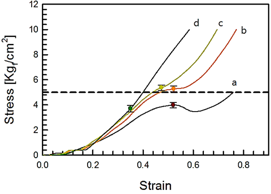
Figure 7: The stress-strain to CCS structure; (a) non-compression; (b) 20%-compression; (c) 30%-compression; (d) 40%-compression. UTM results is given by solid lines; symbols denote yield points; the chain line represents our reference value, 5.
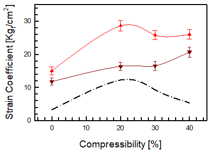
Figure 8: Strain coefficient as a function of compressibility: 20% compression (top orange curve), 30% compression (middle brown curve), and 40% compression (bottom single point curve).
Figure. 8 shows the strain coefficient on the compressibility, which is the slope of the stress-strain curve. The strain coefficient means the resistance capacity to the external compression force and material strength. The lower-triangle and upper-triangle respectively shows the slop of the pre- or post- inflection points and the chain-dot line is the difference of two values. The initial physical property of auxetic pad depends on lower-triangle. The more upper-triangle, the more resistance force to the external compression force. This buckling mode of auxetic pad changes in 20% compression rate and depends on the CCH structure. It is estimated that the maximum influence will be 22% compression rate. The Poisson’s ratio and stiffness curves had a high nonlinearity for unit cell dimensions. This nonlinearity is due to the different stiffness of each cell and the surface contacts of the struts. As the unit cell is gradually compressed, the cell element stays rigid due to higher stiffness and only the vertical strut begins to collapse causing surface contacts among themselves. Eventually, the auxetic hollow structure becomes a solid block and starts behaving like a normal structure. While the pad is pulled, the zig-zag-shaped vertical strut will be straightened and eventually begin stretched while the rhombus-shaped cell components still experience much less deformation. It means that the transition of the structure from the auxetic to non-auxetic normal structure occurs when the surface contact begins when it is compressed and when the vertical strut is fully straightened under tensile load.
The CCS shows a strong ability to regulate its mechanical properties over a quite wide range by tuning geometrical parameters or relative density. In addition, the CCS could exhibit stable auxetic behavior under large deformation, making it easy to predict its deformation even under large deformation. It is found the CCS with 30 degrees possesses the highest energy absorption capacity. In the case of quasi-static (or low-velocity) mode and medium-velocity mode, the energy absorption efficiency of sample 2 is stable at about 50%, which is higher than most cellular materials reported before. In particular, sample 2 shows the highest absorption efficiency under stable quasi-static mode.
The strut thickness has an influence on the variable behavior of auxetic cells. In order to have the soft variable stiffness in the auxetic cell under the given payload, the resistance force for changing behavior should be maintained under the control of strut angle and thickness. To be used for the macro-auxetic cell of a variable stiffness suit, the geometric factor is recommended to be in the negative slope, which means that the structure becomes hard beyond a certain strut angle and flexible below it. Thus, the valid strut angle, thickness, and length should be taken into account under the given payload. This can be seen as a result of the characteristics of the soft auxetic structure unit design applied with different materials. At the beginning of the strength test, a graph with a lower elastic coefficient is drawn, and a higher elastic coefficient is drawn from the moment the force is transferred to the auxetic material. This allows us to observe differences between the propensity of compression strength and elasticity coefficients. The elastic factor range was specified from the moment the force was transferred to the material under each condition, and the compressive strength was measured as the maximum strength value in the 30% strain.
“This research was supported by the Alchemist Project (No. 1415187415, No. 20025750) funded by the Technology Innovation Program funded by the Korea Planning & Evaluation Institute of Industrial Technology (KEIT) and the Ministry of Trade, Industry, & Energy (MOTIE)”.
Dear Editorial Team, Clinical Medical Reviews and Reports. My experience with the journal was highly positive. The peer-review process was rigorous, constructive, and completed in a timely manner. The reviewers provided valuable comments that helped improve the quality and clarity of our manuscript. The editorial office was professional, responsive, and supportive throughout all stages of the publication process. Communication was clear and efficient, and any questions were addressed promptly. Overall, I found the journal to maintain high scientific standards and an excellent publication workflow. I would be pleased to consider submitting future work to this journal. Best wishes from, Elena Popa.

It was my pleasure to submit my testimonial concerning the Reviewer Board of our Scientific Journal “Brain and Neurological Disorders”. The Reviewers focused on some modifications and their contribution was helpful. The ladies of our Editorial Office were also supported my efforts. It was my honor to have such a co-operation and I am looking forward for more collaboration.
Dear Grace Pierce, Editorial Coordinator of Journal of Clinical Research and Reports, Thank you for the speedy and efficient peer review process. I appreciate the fact that your peer reviewers do not take months to respond like with some other journals. I would also like to thank the editorial office for responding quickly to my questions. It is an excellent journal. I plan to submit more manuscripts in the future. Best wishes from, Robert W. McGee

Dear Grace Pierce, Editorial Coordinator of Journal of Clinical Research and Reports, Working with you and your team on our recent publication in JCRR has been a truly wonderful and enjoyable experience. The responses were prompt, and the reviewers were patient, constructive, and highly professional. One reviewer in particular gave me the feeling that a professor was carefully reading and commenting on my coursework, which was deeply touching. The entire process was straightforward and hassle‑free, with no tedious online forms to complete. I highly recommend this journal. Best wishes from, DR Aibing Rao, Head of R&D

I Appreciate the Opportunity to Share my Experience with the Journal of Clinical Research and Reports. The peer review process was timely and constructive, and the feedback provided helped improve the quality of our manuscript. The editorial office was professional, responsive, and supportive throughout the process, ensuring smooth communication and efficient handling of the submission. Overall, it was a positive experience collaborating with your team.

Dear Mercy Grace, Editorial Coordinator of Obstetrics Gynecology and Reproductive Sciences, We would like to express our gratitude for your help at all stages of publishing and editing the article. The editors of the magazine answer all the necessary questions and help at every stage. We will definitely continue to cooperate and publish other works in the Obstetrics Gynecology and Reproductive Sciences! Best wishes from, Alla Konstantinovna Politova,